Hydraulic Breaker in Indiana & Other Heavy Equipment Attachments
Compare technical specs of hydraulic breakers in Indiana limestone quarries to other heavy equipment attachments. Flow rates, PSI, and carrier matching.
Hydraulic breakers in Indiana require auxiliary hydraulic flows between 15 and 120 gallons per minute (GPM) and operating pressures of 1,500 to 2,500 pounds per square inch (PSI), depending on the carrier size. When integrating breakers with other heavy equipment attachments like augers or compactors, fleet managers must verify the excavator's auxiliary circuit capacity and quick coupler compatibility to prevent hydraulic system failure.
This technical specification guide is engineered specifically for Indiana construction fleet managers, excavation contractors, and heavy equipment operators optimizing their attachment inventory for regional geological conditions.
- Indiana limestone requires breakers operating at 1,800 to 2,200 PSI for optimal fracture rates.
- Verify auxiliary hydraulic flow (GPM) before swapping between breakers, augers, and compactors.
- Use automatic quick couplers to reduce attachment changeover time to under 60 seconds.
Core Hydraulic Breaker Specifications for Indiana Excavation
Matching Flow and Pressure to Carrier Weight
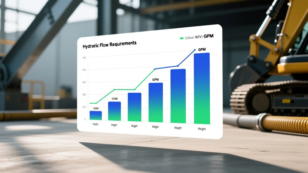
Selecting the correct hydraulic breaker requires matching the attachment to the excavator's operating weight and auxiliary hydraulic output. A 10-ton carrier typically demands a breaker utilizing 25 to 40 GPM. Conversely, a 50-ton excavator requires heavy-duty breakers consuming 90 to 120 GPM. Mismatching these metrics causes cavitation in the hydraulic pump or insufficient impact energy.
Navigating Indiana Limestone and Glacial Till
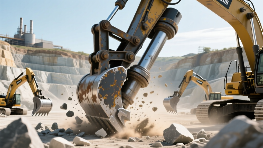
Indiana's geological profile features dense Salem Limestone and abrasive glacial till. Breaking this bedrock necessitates moil-point tools operating at 1,800 to 2,200 PSI. The Association of Equipment Manufacturers (AEM) recommends maintaining a strict 45-degree operating angle to prevent tool binding and side-plate cracking (Association of Equipment Manufacturers). Operators must also adhere to Occupational Safety and Health Administration (OSHA) noise regulations, ensuring breakers remain below 85 decibels (dB) at the operator's station (Occupational Safety and Health Administration).
Key Industry Definitions
Hydraulic Breaker
A hydraulic breaker is a powerful percussion hammer fitted to an excavator for demolishing concrete structures or breaking rock. It is powered by the carrier's auxiliary hydraulic system, utilizing pressurized fluid to drive an internal piston that delivers high-frequency impact energy to a tool bit.
Auxiliary Hydraulic Circuit
An auxiliary hydraulic circuit is a secondary hydraulic system on heavy equipment designed to power attachments. It includes dedicated pumps, control valves, and quick-disconnect couplers, allowing the operator to route pressurized fluid from the carrier to implements like breakers, augers, or grapples.
Comparing Breakers to Other Heavy Equipment Attachments
Fleet managers frequently rotate between hydraulic breakers and other heavy equipment attachments on Indiana job sites. Understanding the distinct hydraulic profiles of each implement prevents system overloads.
Hydraulic Flow Matrix: Breakers vs. Augers vs. Compactors
| Attachment Type | Optimal Flow (GPM) | Operating Pressure (PSI) | Primary Use Case in Indiana |
|---|---|---|---|
| Hydraulic Breaker | 25 - 120 | 1,800 - 2,200 | Fracturing Salem Limestone bedrock |
| Hydraulic Auger | 15 - 45 | 2,500 - 3,500 | Drilling foundation piers in glacial till |
| Vibratory Compactor | 10 - 30 | 500 - 600 | Trench compaction for utility lines |
| Hydraulic Grapple | 20 - 50 | 3,000 - 4,500 | Sorting demolition debris and timber |
Breakers require high flow but moderate pressure. Augers and grapples demand high pressure to generate torque and clamping force, but require lower continuous flow.
Quick Coupler and Auxiliary Hydraulic Integration
Swapping a hydraulic breaker for a vibratory compactor requires robust quick coupler systems. Automatic hydraulic quick couplers reduce attachment changeover time to under 60 seconds. These systems utilize flat-face couplers to prevent soil contamination when disconnecting hoses in muddy Indiana trenching environments.
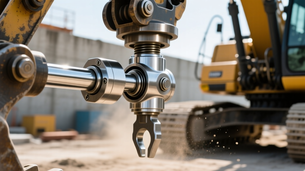
Ensure the carrier's relief valves are adjusted for each specific attachment. Running a 600 PSI compactor on a circuit set to 2,200 PSI for a breaker will rupture the compactor's hydraulic motor.
Pre-Operation Attachment Swap Checklist
- Verify auxiliary hydraulic flow settings on the carrier monitor.
- Inspect flat-face quick couplers for dirt or metal shavings.
- Confirm attachment weight does not exceed the excavator's lift capacity.
- Test the relief valve pressure with a gauge before full engagement.
Frequently Asked Questions
What are the hydraulic flow requirements for breakers vs. other attachments?
Hydraulic breakers typically require 25 to 120 GPM at 1,800 to 2,200 PSI. In contrast, hydraulic augers require lower flow (15 to 45 GPM) but higher pressure (2,500 to 3,500 PSI) to generate the necessary rotational torque for drilling.
How do I match heavy equipment attachments to excavators in Indiana?
Match the attachment's weight to the carrier's lift capacity and verify the auxiliary hydraulic pump's maximum flow output. Consult the excavator's load chart and ensure the combined weight of the attachment and quick coupler does not exceed the machine's tipping load limit.
Which hydraulic breaker brands perform best for Indiana limestone excavation?
Industry leaders like Atlas Copco, Montabert, and NPK manufacture breakers with high blow-frequency ratings ideal for sedimentary rock. Select models featuring auto-strike technology, which prevents the breaker from firing when the tool bit loses contact with the limestone.
Conclusion and Next Steps
Optimizing hydraulic breaker performance alongside other heavy equipment attachments requires precise alignment of flow rates, operating pressures, and carrier weights. Indiana contractors must account for regional geological factors like Salem Limestone when selecting tool bits and setting relief valves. To proceed, audit your current fleet's auxiliary hydraulic output specifications and compare them against the hydraulic flow matrix provided above to identify any mismatched attachments.