Heavy Equipment Welding Repair: Troubleshooting Crack Failures
Diagnose and fix heavy equipment welding repair failures. Learn preheat specs, undermatching filler metals for AR400, and HAZ crack troubleshooting.
Diagnostic Abstract
Cracking in the Heat-Affected Zone (HAZ) remains the most costly failure in heavy equipment welding repair, particularly on high-strength, low-alloy (HSLA) and abrasion-resistant (AR) steels used in excavator buckets, dozer blades, and crane booms. This guide bypasses generic welding advice to provide a metallurgical troubleshooting framework for Hydrogen-Induced Cold Cracking (HICC), transverse restraint failures, and filler metal mismatches. All thermal and consumable specifications align with AWS D14.3/D14.3M standards for earthmoving equipment.
Root Cause Analysis: Hydrogen-Induced Cold Cracking (HICC)
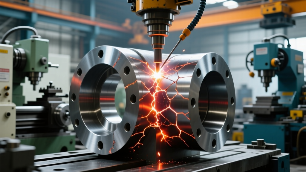
When a heavy equipment welding repair fails 12 to 48 hours after completion, the culprit is almost exclusively HICC, also known as delayed cracking. This phenomenon requires three simultaneous conditions: a susceptible microstructure (martensite), the presence of diffusible hydrogen, and high residual tensile stress.
AR400 and AR500 plates achieve their hardness through quenching and tempering. When you apply an arc, the HAZ rapidly heats and cools. If the cooling rate is too fast, the austenite transforms into untempered martensite—a highly brittle crystalline structure. Simultaneously, moisture from the atmosphere, hydrocarbons on the base metal, or the flux core of the wire introduces hydrogen into the weld pool. As the joint cools, hydrogen migrates to the microscopic stress concentrators in the martensitic HAZ, leading to catastrophic intergranular cracking.
Field Rule: Never rely on visual inspection immediately post-weld. Magnetic Particle Testing (MT) or Dye Penetrant Testing (PT) on AR steels must be delayed a minimum of 24 hours—and ideally 48 hours—to allow diffusible hydrogen to manifest as visible HAZ cracks.
The Undermatching Strategy for Abrasion-Resistant Steels
A critical error in heavy equipment welding repair is attempting to 'match' the tensile strength of the base metal. Welding AR400 (180 ksi tensile) with a 110 ksi or 120 ksi filler metal creates a rigid, unyielding weld bead that transfers all shrinkage stress directly into the weaker HAZ, tearing the base metal apart.
The solution is undermatching: using a lower-strength, higher-ductility filler metal for the root and fill passes, allowing the weld metal to absorb plastic deformation. If surface wear resistance is required, a hardfacing cap is applied only after the structural joint is complete.
| Base Metal | Typical Application | Root/Fill Filler (Undermatched) | Hardfacing Cap (If Required) |
|---|---|---|---|
| ASTM A572 Gr 50 | Chassis, structural frames | ER70S-6 (70 ksi) / E71T-1 | N/A |
| AR400 / Hardox 400 | Excavator buckets, liners | E11018-M (110 ksi) or 309L | Stoody 1105 / Hardox HiTuf |
| AR500 / Hardox 500 | Dozer blades, rock breakers | ER309L (Austenitic SS buffer) | Stoody 1040 / Tungsten Carbide |
| ASTM A514 (T1) | Crane booms, lifting lugs | E11018-M (Strict preheat req.) | N/A (Structural only) |
Note: For AR400 structural joints under high dynamic loading, austenitic stainless wires like ER309L are increasingly used as a buffer layer. The high ductility and hydrogen solubility of the austenitic matrix trap hydrogen and prevent it from migrating into the HAZ. For advanced consumable selection, refer to the Lincoln Electric process and theory documentation on high-strength steel metallurgy.
Thermal Management: Preheat and Interpass Protocols
Controlling the cooling rate is the only way to prevent martensite formation in the HAZ. You must calculate the Carbon Equivalent (CE) of the specific plate batch. Most AR400 falls between 0.45 and 0.55 CE.
Step-by-Step Thermal Execution
- Preheat Verification: Do not use temperature-indicating crayons (Tempilstiks) on the weld joint itself; the wax can introduce carbon and hydrogen into the puddle. Apply crayons 2 inches away from the joint, or use a calibrated infrared pyrometer. For 1-inch AR400, target 250°F. For AR500 or thicknesses over 1.5 inches, target 350°F to 400°F.
- Soak Time: Heating the surface is insufficient. Allow 1 hour of soak time per inch of thickness to ensure the core of the plate reaches the target temperature, preventing a steep thermal gradient.
- Interpass Temperature Control: This is where many field repairs fail. While minimum preheat prevents cracking, exceeding the maximum interpass temperature (usually 450°F for AR steels) will over-temper the base metal, destroying its abrasion resistance and yield strength. Monitor continuously between passes.
- Post-Weld Slow Cooling: Never let an AR steel weld air-cool in an open field or cold shop. Immediately cover the joint with 2-inch thick ceramic fiber blankets (e.g., Cerablanket) to force a slow cooling rate, allowing hydrogen to diffuse out of the metal lattice before martensite can form.
Defect Signature Diagnostic Guide
When a weld fails, the geometry and location of the crack dictate the corrective action for the next repair attempt.
Transverse Cracking (Perpendicular to the weld bead)
Cause: High longitudinal restraint combined with hydrogen embrittlement. The joint cannot shrink along its length as it cools.
Corrective Action: Implement a backstep welding sequence. Weld 4 inches in the opposite direction of the overall travel, then move forward 2 inches and repeat. This keeps the localized joint slightly open and reduces residual tensile stress. Increase preheat by 50°F.
Longitudinal Cracking (Parallel to the weld bead, usually in the root)
Cause: Inadequate root penetration, high sulfur/phosphorus in the base metal causing centerline segregation, or an excessively deep and narrow weld bead profile (depth-to-width ratio > 1.0).
Corrective Action: Widen the joint bevel from 45° to 60°. Switch from 100% CO2 shielding gas to a 75% Argon / 25% CO2 mix (C25) if using GMAW, which reduces the finger-penetration profile and creates a broader, shallower bead that resists centerline tearing.
HAZ Toe Cracking (Originating at the fusion line)
Cause: Classic hydrogen-induced cold cracking exacerbated by a sharp geometric notch at the weld toe, creating a massive stress concentrator.
Corrective Action: Grind the weld toe to a smooth 1/16-inch radius transition into the base metal. Apply a cosmetic 'temper bead' over the toe area using low heat input to locally temper the martensite without adding structural load.
Field vs. Shop Repair: Economic and Metallurgical Trade-offs
Deciding whether to execute a heavy equipment welding repair in the field or transport the component to a shop involves analyzing both metallurgical risk and downtime economics.
A field repair on a 50-ton excavator boom avoids the $4,000–$8,000 cost of crane mobilization and transport, and prevents the $1,500–$3,000 per day machine downtime penalty. However, field environments introduce severe variables: wind stripping shielding gas (causing porosity and subsequent hydrogen ingress), ambient temperatures dropping below 40°F, and inability to perform post-weld heat treatment (PWHT).
According to Miller Welds technical resources on field fabrication, if ambient wind exceeds 5 mph, field welders must deploy physical windbreaks; otherwise, the gas coverage on FCAW and GMAW processes is compromised, leading to subsurface porosity that acts as a nucleation site for fatigue cracks under cyclic loading.
The Decision Framework:
- Execute in Field if: The repair is on a non-critical, easily accessible attachment point (e.g., bucket linkage, wear liner), preheat can be maintained with propane torches, and the component can be blanket-cooled safely.
- Transport to Shop if: The repair involves T1 (A514) crane booms, thick-section AR500 cutting edges, or requires full-penetration ultrasonic testing (UT) where shop-positioning (1G/2G) is required to guarantee root fusion.
Advanced FCAW Parameters for Dirty Field Joints
Field repairs rarely feature perfectly clean, machined bevels. You are often welding over gouged-out fatigue cracks with residual carbon from carbon-arc gouging. When utilizing Flux-Cored Arc Welding (FCAW) with an E71T-1 or E11018-M wire, parameter tuning is critical to avoid slag inclusions that mimic crack failures on radiographic inspections.
Maintain a Contact-Tip-to-Work Distance (CTWD) of exactly 3/4-inch to 1-inch. A shorter stick-out causes the flux to overheat and burn off before reaching the puddle, losing its deoxidizers and resulting in porosity. A longer stick-out causes excessive electrical resistance heating, melting the wire prematurely and causing 'stubbing' and slag entrapment. Use a drag (pull) technique at a 10-to-15-degree angle, which allows the flux to melt evenly and the slag to float to the surface behind the arc, rather than being pushed ahead into the unfused joint root.