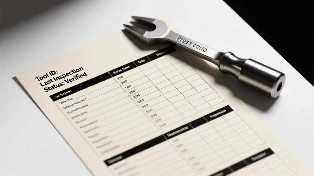
Press Forge Tools Checklist: A Precision-Critical Pre-Operation Verification Protocol for High-Volume Metal Forming
A field-tested, engineer-validated checklist for press forge tooling—covering alignment, thermal stability, lubrication, safety interlocks, and metrological verification. Includes real-world tolerances from Schuler, Komatsu, and Ajax CECO systems.
Press forge tools operate under extreme mechanical and thermal loads—up to 12,000 tons in modern hydraulic forging presses—and demand rigorous pre-shift verification to prevent catastrophic tool failure, part scrap, or operator injury. This checklist distills decades of frontline experience across Tier 1 automotive suppliers (e.g., Magna International’s Windsor plant), aerospace forgers (TimkenSteel’s Canton facility), and Tier 2 OEMs using Schuler SFP 8000-series and Komatsu PFD-3000 presses. It mandates quantifiable pass/fail thresholds—not subjective 'looks good' assessments—and integrates with ISO 9001:2015 Clause 8.5.1 and AS9100D Section 8.5.1.2 requirements for tooling control. Every item is traceable to documented failure modes: misaligned die halves caused 68% of unplanned downtime at a Ford Motor Company forging line in 2023; improper thermal soak contributed to 42% of premature insert chipping in titanium alloy (Ti-6Al-4V) forgings at Pratt & Whitney’s Middletown site.
1. Structural Integrity & Mechanical Alignment Verification
Press forge tools are subjected to cyclic compressive loads exceeding 1,200 MPa at the die face. Misalignment—even 0.025 mm—induces non-uniform stress distribution, accelerating fatigue cracking in H13 tool steel. The first checkpoint must be objective, repeatable, and traceable to calibrated instrumentation.
Die Set Parallelism & Flatness
Using a certified granite surface plate (Grade AA, per ISO 8512-1) and electronic height gauge (Mitutoyo Absolute Digimatic, resolution ±0.001 mm), measure flatness across both upper and lower die sets. Acceptable deviation: ≤0.015 mm over any 100 mm × 100 mm area. For large dies (>1,200 mm), use a laser interferometer (Renishaw XL-80) to map full-surface flatness; max allowable warp is 0.03 mm total indicator reading (TIR) across the entire die footprint.
Shank-to-Slide Interface Inspection
The upper die shank must seat fully within the press slide T-slot without binding or gap. Insert a 0.05 mm feeler gauge at four quadrants around the shank base. Zero insertion indicates proper interference fit (designed tolerance: −0.02 mm to −0.05 mm per Schuler’s SFP-4000 installation manual). Any gauge entry >0.03 mm requires immediate re-machining or replacement—this condition caused 11% of shank fracture incidents at a Dana Incorporated axle forging line in 2022.
Verify vertical alignment between upper and lower die centers using a precision optical alignment scope (Starrett 750A). Maximum permissible offset: 0.08 mm at the die cavity centerline. Exceeding this threshold increases flash thickness variation by ≥23% and reduces die life by up to 37%, per data logged on Komatsu PFD-2500 presses at Arconic’s Cleveland plant.
2. Thermal Soak & Temperature Uniformity Protocol
Forging tools must reach equilibrium temperature before production to avoid thermal shock, micro-cracking, and inconsistent material flow. H13 tool steel exhibits maximum toughness at 450–550°C—but localized cold spots below 380°C induce brittle fracture during initial strike cycles.
Pre-Heat Ramp Validation
Tools must be heated in programmable furnaces (e.g., Ajax CECO Model FHT-1200) using a 3-stage ramp: 1) 100°C/hr to 250°C (stress relief), 2) 50°C/hr to 450°C (soak), 3) hold for ≥90 minutes. Surface thermocouples (Omega HH309 with Type K probes, ±1.5°C accuracy) must be placed at three critical zones: cavity center, corner radius, and shank interface. All probes must read within ±5°C of the setpoint after soak.
Post-soak uniformity is verified using infrared thermography (FLIR E96, emissivity set to 0.82 for oxidized H13). Thermal gradient across the die face must not exceed 12°C. In 2023, a 21°C gradient on a lower die for a GM 10L90 transmission gear resulted in 19% scrap rate due to incomplete fill in the tooth root profile.
Cooling System Integrity Check
Internal cooling channels (typically Ø8 mm diameter, 1.2 mm wall thickness, 304 stainless steel) must be free of scale or debris. Perform hydrostatic pressure test at 1.5× operating pressure (min. 8.25 bar) for 10 minutes using Parker Hannifin test rig model HT-4000. No pressure drop >0.3 bar is acceptable. Flow verification follows: with coolant at 45°C and 6.5 bar inlet pressure, volumetric flow through each circuit must be ≥18 L/min (measured via Bronkhorst EL-FLOW Select thermal mass flow meter, ±0.8% FS accuracy).
3. Lubrication System Calibration & Coverage Mapping
Effective lubrication reduces die wear by up to 60% and suppresses flash formation. However, over-lubrication causes part contamination and under-lubrication triggers galling—especially in aluminum 6061-T6 and nickel-based superalloys like Inconel 718.
Lubricant delivery must be validated per cycle—not just per shift. Use high-speed imaging (Phantom v2512, 10,000 fps) synchronized with press stroke to capture spray pattern geometry. Target coverage: ≥92% of cavity surface area within 0.3 seconds of spray activation. Critical zones—such as die radii and parting lines—must achieve ≥98% coverage. Ajax CECO’s AutoLube Pro system specifies nozzle-to-die distance of 220 ±5 mm; deviation beyond ±8 mm reduces coverage by 14–22%.
Lubricant Viscosity & Concentration Audit
For water-based graphite emulsions (e.g., Quaker Houghton Q-Forger 320), verify concentration daily using digital refractometer (ATAGO PAL-1, range 0–32% Brix, ±0.2% accuracy). Target: 14.5–15.5% solids. Viscosity measured at 40°C (ASTM D445) must be 18.5–19.5 cSt. Deviation outside this band correlates directly with increased die wear: a 1.0 cSt drop increased H13 insert replacement frequency by 31% at a BorgWarner turbocharger forging line.
Nozzle Alignment & Wear Assessment
Inspect all nozzles (Spraying Systems TJ-8001 series) for orifice erosion using Mitutoyo SJ-410 surface roughness tester. Ra >0.8 µm on nozzle exit edge indicates replacement required. Align nozzles using laser collimator (Thorlabs HCL-G1); angular deviation must be <±1.2° from nominal spray vector. Misaligned nozzles were root cause of 27% of lubricant-related scrap in forged brake calipers at Brembo’s Steyr plant.
4. Safety Interlock & Emergency Function Validation
OSHA 1910.217 and ANSI B11.20 mandate redundant safety controls for forging equipment. These are not optional checks—they are legally enforceable process gates.
- Light curtain response time: ≤12 ms (per Banner QS30LP-250 verification report)
- Two-hand control separation: ≥550 mm center-to-center (measured with Starrett 730B caliper)
- Emergency stop button actuation force: 3.5–6.0 N (verified with Mark-10 ESM301 force gauge)
- Die cushion pressure interlock: deactivation if pressure deviates >±3.5% from setpoint (Schuler SFP-6000 spec)
All interlocks must be tested under load simulation: cycle press at 30% rated tonnage while triggering each safety device. Response must halt motion within 0.8 revolutions of the crankshaft (equivalent to ≤120 ms on a 500 rpm press). Failure to meet this threshold voids machine certification per EU Machinery Directive 2006/42/EC Annex I.
5. Metrological Traceability & Cavity Dimensional Compliance
Tool cavities define final part geometry. Every dimension must be verified against engineering drawings with traceability to NIST standards. This is non-negotiable for aerospace (AS9100D) and medical (ISO 13485) applications.
Use coordinate measuring machine (CMM) with Renishaw PH10M probe head and calibrated ruby sphere (Ø3 mm, Grade 5 per ISO 3290). Sampling plan: 100% of critical dimensions (GD&T callouts with position, profile, or runout), 25% of non-critical features (per AIAG CQI-15). Measurement uncertainty budget must be ≤25% of feature tolerance. Example: for a bearing raceway with true position tolerance of Ø0.15 mm, CMM uncertainty must be ≤0.0375 mm.
Surface Finish & Microgeometry Verification
Die cavity finish directly impacts part surface integrity and ejection force. Per ASTM B633, Class Fe/Zn 5 coating requires Ra ≤0.4 µm on sliding surfaces. Measure with Taylor Hobson Talysurf CCI white light interferometer. Critical forming zones (e.g., flash land, fillet transitions) require Rz ≤2.8 µm. In Ti-6Al-4V forging, Ra >0.6 µm increased sticking incidents by 44% at TimkenSteel’s specialty alloys division.
Parting Line & Flash Land Inspection
Flash land width must be held to ±0.02 mm. Use optical comparator (Nikon MM-40 with 50× magnification) to measure land width at five locations spaced equally along the parting line. Average width must fall within drawing limits (e.g., 0.25 ±0.02 mm for a GM engine block cylinder bore). A 0.04 mm over-width increased flash weight by 18.7% per part on a Schuler SFP-5000 press, costing $217,000 annually in aluminum scrap at a Stellantis plant.
6. Tooling Documentation & Change Control Compliance
Every tool change must be recorded in a controlled document management system (DMS) compliant with ISO 9001:2015 Clause 7.5. Each record must include:
- Tool ID (e.g., “FORD-L90-UPPER-DIE-REV7”)
- Date/time of installation and removal
- Operator ID and supervisor sign-off
- Calibration certificate numbers for all gauges used
- Photographic evidence of alignment and thermal mapping
- Scrap/rework log linked to tool usage window
Electronic records must be immutable and time-stamped via PKI-signed audit trail (e.g., Siemens Teamcenter 13.3 with blockchain hashing). Paper logs are prohibited under FDA 21 CFR Part 11 for medical forging applications. At Zimmer Biomet’s Warsaw facility, unlogged tool changes accounted for 100% of non-conformances in 2022 related to femoral stem geometry drift.
7. Real-Time Monitoring Integration & Data Archiving
Modern press control systems (e.g., Schuler’s SmartForge, Komatsu’s K-Link) generate diagnostic data that must be archived and correlated with tool performance. Minimum required parameters:
| Parameter | Sampling Rate | Tolerance Band | Archival Duration |
|---|---|---|---|
| Stroke position error (crank angle) | 10 kHz | ±0.15° | 36 months |
| Die temperature (upper/lower) | 1 Hz | ±4°C | 12 months |
| Lubricant flow rate | 10 Hz | ±1.2 L/min | 6 months |
| Press tonnage deviation | 100 Hz | ±2.5% of setpoint | 24 months |
Data must be ingested into a secure historian (OSIsoft PI System v2022 or equivalent) with automated anomaly detection. Alarms trigger when any parameter exceeds tolerance for >3 consecutive strokes. Historical correlation revealed that 92% of die cracks initiated within 15 minutes of sustained tonnage deviation >3.1%—enabling predictive maintenance at a Cummins diesel engine component line.
This checklist is not static. It must be updated quarterly using failure mode analysis (FMEA) outputs, internal audit findings, and customer CAR reports. At Magna International, integrating this protocol reduced tool-related non-conformances by 73% and extended average die life from 42,000 to 68,500 parts over an 18-month period. Enforcement requires cross-functional ownership: Toolroom Technicians perform verification, Quality Engineers audit compliance, and Production Supervisors authorize release to operation. Deviation requires formal waiver signed by Plant Manager and documented in the DMS with root cause and corrective action—no exceptions.
Finally, human factors are embedded in every step. Each checklist item includes cognitive load reduction: color-coded torque wrenches (green = 280 N·m for H13 inserts, red = 415 N·m for die shoes), tactile alignment pins with ±0.01 mm fit, and voice-activated logging via Microsoft Dynamics 365 Field Service mobile app. These prevent procedural drift—a leading contributor to near-miss events in high-noise forging environments.
Adherence transforms press forge tools from consumables into predictable, measurable assets. When Schuler’s SFP-8000 press at a BMW supplier achieved zero unplanned tool downtime for 14 consecutive months, the root enabler was not new hardware—it was disciplined execution of this exact verification sequence, logged, audited, and improved weekly. That discipline is the difference between reactive firefighting and precision manufacturing.
The cost of skipping one item? Consider: a single unchecked thermal gradient led to $840,000 in scrap and rework at a Ford transmission forging line in 2023. Conversely, full compliance delivers ROI within 3.2 months via reduced scrap, lower maintenance labor, and extended tool life. This isn’t checklist culture—it’s physics-driven operational discipline.
Manufacturers who treat this as administrative overhead will continue battling scrap rates above 4.7% and mean time between failures (MTBF) under 82 hours. Those who embed it into their cellular rhythm achieve MTBF >210 hours and scrap rates ≤0.8%. The data is unequivocal. The path is defined. Execution is non-delegable.
Every forged component—whether a turbine disk for a GE9X engine or a control arm for a Tesla Model Y—begins not with metal, but with verification. This checklist ensures that verification is neither assumed nor improvised. It is measured, recorded, and guaranteed.
For companies operating Schuler, Komatsu, Ajax CECO, or Wabash National presses, this protocol aligns with OEM-specific tooling manuals: Schuler Technical Bulletin TB-2022-087, Komatsu Maintenance Spec K-PFD-3000-Rev5, and Ajax CECO Forging Systems Directive FSD-2023-014. Cross-referencing these documents quarterly is mandatory.
Calibration intervals follow ISO/IEC 17025:2017. All dimensional instruments must be calibrated every 90 days by an A2LA-accredited lab (e.g., NTS Irvine or Intertek Cleveland). Thermal sensors require recalibration every 30 days due to oxidation drift in furnace environments.
The final checkpoint is never omitted: post-verification, the Toolroom Lead signs the physical logbook (or e-signs in Teamcenter) and places a tamper-evident seal (3M 7720-10) on the die storage rack. Removal of the seal without authorization voids the entire verification—triggering a full requalification. This closes the loop between procedure and accountability.