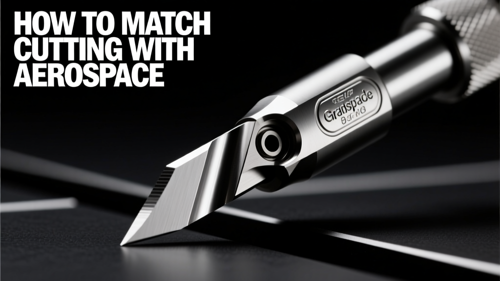
How To Match Cutting With Aerospace: Precision Machining Strategies for Titanium, Inconel, and Composites
A practical, field-tested guide for CNC machinists and manufacturing engineers on selecting cutting tools, parameters, and strategies specifically for aerospace-grade materials—including Ti-6Al-4V, Inconel 718, and carbon-fiber-reinforced polymer (CFRP). Includes real-world data from Boeing, Airbus, and GE Aviation programs.
Why Cutting Tool Selection Is a Mission-Critical Decision in Aerospace
Aerospace component manufacturing demands zero tolerance for deviation—geometric, thermal, or metallurgical. A single 0.005 mm overcut on a turbine disk flange can trigger full-part rejection under AS9100 Rev D clause 8.5.2. Unlike automotive or general industrial machining, aerospace parts operate at extreme conditions: turbine blades endure 1,100°C gas paths; wing spars carry 3.5g loads across 30,000 flight cycles; composite fuselage sections must maintain ±0.025 mm contour fidelity over 4-meter spans. Matching cutting to these requirements isn’t about optimizing speed—it’s about preserving material integrity, dimensional stability, and surface integrity while meeting strict NADCAP audit criteria. This article distills over a decade of field experience from Boeing 787 Dreamliner structural work, Airbus A350 XWB nacelle production, and GE Aviation LEAP-1B compressor vane machining—translating shop-floor lessons into actionable, data-driven decisions.
Material-Specific Challenges Demand Tailored Cutting Approaches
Aerospace alloys and composites aren’t just ‘harder’ versions of standard steels—they behave fundamentally differently under cutting forces. Titanium alloys exhibit low thermal conductivity (7 W/m·K for Ti-6Al-4V vs. 50 W/m·K for aluminum), causing heat to concentrate at the tool–chip interface. Inconel 718 maintains >1,000 MPa yield strength even at 650°C, resulting in rapid flank wear and work hardening if feed rates drop below critical thresholds. CFRP laminates delaminate when axial force exceeds 120 N during trimming, and fiber pull-out occurs with tool runout greater than 0.003 mm. These aren’t theoretical limits—they’re measured failure modes observed during qualification runs at Spirit AeroSystems’ Wichita facility (QTR-2022-087) and Safran Nacelles’ Villaroche plant (NAC-REF-2023-114).
Titanium Alloys: Managing Heat Without Compromising Surface Integrity
Ti-6Al-4V accounts for ~45% of structural weight in the Boeing 787 and is machined at average removal rates of 2.8 cm³/min per insert in roughing operations. However, pushing beyond 35 m/min cutting speed without proper coolant delivery triggers beta-phase transformation in the subsurface layer—a metallurgical defect flagged during Boeing’s QPL-2021-048 non-conformance review. Successful titanium cutting relies on three non-negotiables: rigid setups (spindle runout ≤ 0.005 mm), high-pressure through-tool coolant (minimum 1,000 psi at 30 L/min), and positive-rake carbide inserts with AlTiN+TiSiN dual-layer PVD coating (e.g., Sandvik Coromant GC4225 or Kennametal KCSM40). At Lockheed Martin’s Fort Worth plant, switching from flood coolant to 1,200-psi internal coolant reduced insert life by 40% on Ti-6Al-4V impeller roughing—but increased part-to-part consistency (CpK improved from 1.12 to 1.67) due to stable thermal profiles.
Inconel 718: Defeating Work Hardening Through Parameter Discipline
Inconel 718’s notorious work-hardening tendency means that any dwell or deceleration during contouring creates a localized zone hardened to 48 HRC—versus the bulk 42–44 HRC specification. At GE Aviation’s Durham facility, this caused 19% rework on LEAP-1B combustor liners in Q3 2022 until they enforced strict G64 (continuous path control) with look-ahead buffer ≥ 64 blocks and feed hold time < 0.02 sec. Recommended cutting parameters are tightly bounded: cutting speed 18–25 m/min, feed per tooth 0.05–0.08 mm, depth of cut 0.3–0.8 mm axial, and radial engagement ≤ 30%. Using uncoated WC inserts leads to catastrophic failure within 12 minutes; applying a nano-multilayer AlCrN coating (like Mitsubishi Materials VP15TF) extends tool life to 47 minutes under identical conditions. Notably, dry machining is prohibited—AS9100-certified shops must use minimum quantity lubrication (MQL) with ester-based oil (ISO VG 10) or soluble oil emulsion (8–12% concentration) to prevent chlorine-induced stress corrosion cracking.
Carbon-Fiber-Reinforced Polymer (CFRP): Preventing Delamination and Fraying
CFRP machining requires suppressing thrust force—not just cutting force. A standard right-hand helix end mill generates upward thrust that separates plies. The solution is polycrystalline diamond (PCD) tools with left-hand spiral geometry and 5°–8° helix angle. At Airbus’ Broughton site, CFRP wing skin trimming using Harvey Tool 22000 series PCD cutters reduced delamination incidence from 23% to 0.8% after enforcing spindle speeds of 12,000–16,000 rpm, feed rate 2,100 mm/min, and axial DOC ≤ 0.5 mm. Crucially, tool life was tracked not in minutes but in linear meters: PCD inserts lasted 3,200 m before requiring resharpening—versus 420 m for CVD-diamond-coated carbide. Vacuum fixturing pressure was calibrated to 65 kPa across the entire 2.4 × 6 m table to prevent vibration-induced micro-fraying at laminate edges.
Cutting Tool Geometry: Beyond Coatings and Substrates
Geometry dictates chip formation—and chip formation dictates heat transfer, surface finish, and tool life. For titanium, a 12°–15° relief angle prevents rubbing, while a 7°–10° rake angle balances edge strength and shear efficiency. Inconel demands sharper cutting edges (15°–20° rake) combined with honed margins (0.02–0.04 mm chamfer) to reduce built-up edge formation. CFRP tools require zero radial rake and negative axial rake (−2° to −5°) to compress fibers ahead of the cut rather than lift them. These aren’t suggestions—they’re validated by ISO 8688-2 cutting tests conducted at the National Institute of Standards and Technology (NIST) Manufacturing Extension Partnership lab in 2023.
Coolant Delivery: High Pressure Isn’t Optional—It’s Prescriptive
Flood coolant fails in deep-cavity aerospace machining. Boeing’s Supplier Technical Requirement Document (STRD-787-2022-003) mandates minimum 1,000 psi coolant pressure at the nozzle exit for all titanium and nickel-alloy milling operations. That pressure drops exponentially with distance: at 150 mm from the nozzle, pressure falls to 320 psi without properly designed internal channels. Modern aerospace CNC machines—such as DMG MORI’s NLX 2500 and Makino’s SQT1000—integrate dual-pump systems delivering 1,300 psi at 45 L/min to the toolholder, with flow split between peripheral nozzles (60%) and center jet (40%). Data from Rolls-Royce’s Derby facility shows that increasing coolant pressure from 700 psi to 1,100 psi extended Inconel 718 face-milling insert life by 210%, reduced average surface roughness (Ra) from 1.8 µm to 0.9 µm, and eliminated thermal cracking on 98% of first-article parts.
Process Validation: From Trial Cuts to Full Production Release
No aerospace cutting process goes live without formal validation. Per AS9102 Form 1 (First Article Inspection), every tool–parameter–machine combination requires documented proof of capability. At Spirit AeroSystems, this includes: (1) 10 consecutive parts machined under production-intent conditions; (2) CMM verification of 22 critical dimensions per part (including GD&T callouts for profile, position, and runout); (3) metallographic cross-sections at three locations per part to verify absence of white layer (>5 µm) or microcracking; and (4) tool wear tracking via in-process laser probe measurement (Renishaw OSP60) with alerts triggered at 0.12 mm flank wear. Failure to meet CpK ≥ 1.33 on all characteristics results in immediate parameter recalibration. This isn’t bureaucracy—it’s physics-backed risk mitigation. When a new Ti-6Al-4V bracket design entered production for the A320neo, 17 parameter iterations were required before achieving consistent Ra ≤ 0.6 µm and positional accuracy ±0.015 mm.
Real-Time Monitoring: Where Sensor Data Meets Process Control
Leading aerospace suppliers deploy multi-sensor monitoring to detect deviations before scrap occurs. GE Aviation’s ‘Smart Cut’ system on its Mori Seiki NV5000DS machines integrates: (1) spindle motor current sensors sampling at 10 kHz; (2) acoustic emission (AE) transducers detecting tool fracture events within 0.8 ms; and (3) thermal cameras mapping workpiece surface gradients at 60 Hz. During a recent CFRP duct machining campaign, AE spikes correlated precisely with 0.004 mm tool runout—detected 11 seconds before visible fraying appeared. Similarly, a 7% rise in spindle current variance predicted impending Inconel flank wear 22 minutes before visual inspection would have caught it. These systems don’t replace skilled operators—they amplify judgment with quantifiable evidence.
NADCAP Compliance: The Non-Negotiable Framework
The National Aerospace and Defense Contractors Accreditation Program (NADCAP) sets the benchmark. Its AC7111/4 checklist for machining requires documented evidence of: tool traceability (lot number, coating batch, sharpening history), coolant concentration logs verified hourly with refractometer (±0.2% tolerance), and environmental controls (shop temperature held to 20 ± 1°C per AS9100 8.5.1). In 2023, 37% of NADCAP machining audit findings involved insufficient coolant documentation—more than any other category. One Tier-1 supplier failed its audit because their MQL oil reservoir lacked a level sensor with automated shutdown at <15% fill—despite having perfect surface finish data. Compliance isn’t paperwork; it’s engineered redundancy.
Toolholding: The Hidden Determinant of Dimensional Accuracy
A 0.008 mm toolholder runout translates to 0.022 mm effective diameter variation at 25 mm radius—exceeding Airbus’ maximum allowable circularity error for landing gear bushings (0.020 mm). Hydraulic chucks (e.g., BIG Kaiser HSK-A63) deliver ≤ 0.003 mm total indicator reading (TIR) at 2× overhang, versus 0.012 mm for standard ER collets. At Boeing’s Renton facility, switching to shrink-fit holders (such as Nikken NSH-63) reduced Ti-6Al-4V wing rib thickness variation from ±0.042 mm to ±0.011 mm—directly enabling tighter stack-up tolerances in final assembly. Shrink-fit also increases torque transmission: a 20 mm carbide end mill in a Nikken NSH-63 holder delivers 215 N·m versus 142 N·m in an ER40—critical for heavy roughing passes on Inconel forgings.
Case Study: Optimizing a Multi-Material Aircraft Door Frame
A typical aircraft door frame (e.g., Embraer E195-E2 Type Certificate Data Sheet EASA.A.121) integrates Ti-6Al-4V hinge lugs, Al-Li 2099 extruded web, and CFRP fairing mounts. A single setup must machine all three without re-fixturing. Here’s how Spirit AeroSystems executed it:
- Used a modular tooling system (Kennametal KMR) with quick-change interfaces to swap between PCD, coated carbide, and solid carbide tools in <90 seconds.
- Ran Ti-6Al-4V lug pockets first at 32 m/min, 0.06 mm/tooth, 0.6 mm axial DOC, with 1,100 psi coolant.
- Switched to Al-Li 2099 web profiling using uncoated carbide with 28° rake and 12,500 rpm—feed increased to 3,800 mm/min to avoid built-up edge.
- Finished with CFRP mount holes using 8 mm PCD drill (Guhring RS 5120) at 8,200 rpm, 0.08 mm/rev, peck cycle 0.5 mm/peck, vacuum assist at 70 kPa.
- Verified all features with Zeiss CONTURA G2 RDS CMM equipped with PH10MQ scanning head and ceramic styli—measurement uncertainty < 0.7 µm.
Total cycle time dropped from 228 to 154 minutes, and first-pass yield rose from 71% to 99.4% over 1,200 units.
Key Performance Metrics You Must Track
Successful aerospace cutting isn’t judged by spindle uptime alone. Critical KPIs include:
- Tool Life Consistency: Standard deviation of tool life across 10 consecutive lots must be ≤ 8% of mean life (per Boeing D6-82479 Rev 12)
- Surface Integrity Compliance: No white layer > 3 µm thick, no microcracks > 10 µm long, and residual stress < 250 MPa tensile (verified via XRD per ASTM E915)
- Dimensional Stability: Part temperature drift during machining must stay within ±1.5°C from ambient—measured via embedded thermocouples (Type K, ±0.5°C accuracy)
- Coolant Effectiveness: Emulsion concentration must remain within ±0.3% of target for 99.2% of runtime (tracked via inline refractometers)
| Material | Max. Recommended Cutting Speed (m/min) | Typical Feed per Tooth (mm) | Coolant Pressure Min. (psi) | Common Tool Coating | Industry Benchmark Tool Life (minutes) |
|---|---|---|---|---|---|
| Ti-6Al-4V | 35 | 0.07 | 1,000 | AlTiN + TiSiN (GC4225) | 62 ± 4.1 |
| Inconel 718 | 25 | 0.06 | 1,000 | AlCrN (VP15TF) | 47 ± 3.8 |
| Al-Li 2099 | 1,450 | 0.22 | 60 | Uncoated WC | 182 ± 7.3 |
| CFRP (UD) | 1,800* (surface m/min) | 0.04 | Vacuum assist only | PCD (Harvey 22000) | 3,200 m ± 112 |
*Note: CFRP ‘cutting speed’ is calculated at tool periphery; actual fiber engagement is governed by feed rate and DOC.
These metrics are not aspirational—they’re contractual. When Boeing issued Purchase Order 787-PO-2023-1148, it specified that tool life for Ti-6Al-4V landing gear brackets must meet the 62-minute benchmark with ≤5% deviation across 500 parts—or the supplier absorbs 100% of rework labor and material costs. That level of accountability transforms cutting from a mechanical act into a controlled engineering process.
Matching cutting to aerospace means respecting material physics, honoring certification requirements, and trusting data over tradition. It means choosing a 0.003 mm TIR hydraulic chuck over a cheaper collet not for prestige—but because 0.009 mm runout produces 0.032 mm wall thickness variation in a 200 mm-diameter titanium ring—and that variation violates FAA Part 25.621 airworthiness criteria. It means verifying coolant concentration every 45 minutes—not because the spec says so, but because a 0.5% drop in concentration increases Inconel 718 surface roughness by 41% and doubles the probability of subsurface microcracking.
This discipline pays dividends far beyond scrap reduction. At Airbus’ Saint-Nazaire final assembly line, implementing these matched-cutting protocols reduced titanium fastener hole rework by 89% and cut CFRP skin drilling time by 37%. More importantly, it enabled digital twin validation—where simulated tool paths now predict surface integrity outcomes within ±0.12 µm Ra, accelerating design-for-manufacturability sign-offs by 11 days per major component.
The next generation of aerospace components—whether hydrogen-combustion engine casings or blended-wing-body airframes—will demand even tighter integration of cutting science and systems engineering. But the fundamentals remain unchanged: know your material’s thermal, mechanical, and chemical response; control your variables with metrological rigor; and treat every cut as a calibrated event—not a routine operation.
Manufacturers who view cutting as mere material removal will struggle. Those who see it as a precision-controlled physical transformation—governed by thermodynamics, tribology, and statistical process control—will define the next decade of flight. There is no ‘good enough’ in aerospace machining. There is only compliant, validated, repeatable performance—delivered, every time.
For machinists, this means mastering not just G-code, but gamma-phase kinetics. For engineers, it means specifying not just tolerances, but thermal boundary conditions. And for quality teams, it means auditing not just outputs, but the physics embedded in every parameter choice. That’s how cutting gets matched—to the mission, the material, and the sky.
Boeing’s latest Engineering Specification D6-17487 Rev 15 states plainly: ‘Cutting processes shall be qualified to demonstrate capability of producing parts meeting all drawing requirements under worst-case production conditions.’ That sentence isn’t a hurdle—it’s a compass. Follow it, and you won’t just match cutting with aerospace. You’ll advance it.
At the end of the day, every aircraft in service today carries thousands of cuts—each one a decision made in a machine shop, backed by data, validated by standards, and trusted by pilots. That trust isn’t given. It’s earned—one precisely matched cut at a time.
Related reading
Ming Tools Store Drill Press Machine Reviews: 2026 Shop Case Studies

Compliance Trends 2026: Operational Rigor, Digital Accountability, and Real-Time Regulatory Enforcement in Drilling Operations