CNC Machine Control Software: Architecture and Execution Specs
Explore the technical architecture of CNC machine control software, detailing look-ahead algorithms, spline interpolation, and closed-loop servo execution.
The Tripartite Architecture of Modern CNC Control Software
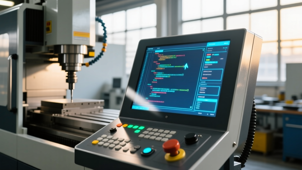
At its core, CNC machine control software is not a single monolithic program, but a tightly integrated real-time operating system (RTOS) divided into three distinct computational domains: the Numerical Control Kernel (NCK), the Programmable Logic Controller (PLC), and the Human Machine Interface (HMI). Understanding how these domains interact is critical for optimizing cycle times and surface finishes in high-speed machining.
Architecture Insight: The NCK handles trajectory generation and interpolation, the PLC manages discrete I/O (coolant, tool changers, M-codes), and the HMI renders the GUI. In modern systems like the Siemens Sinumerik ONE, these three domains run on a single multi-core industrial PC, utilizing shared memory architectures to achieve sub-millisecond communication latency between the PLC and NCK.NCK and the Interpolation Engine
The NCK is the mathematical heart of the control software. It reads G-code blocks, applies coordinate transformations (such as TRAORI for 5-axis kinematics), and calculates the exact positional setpoints for each servo drive. The NCK operates on a strict real-time interrupt cycle, typically executing every 1 to 4 milliseconds, ensuring deterministic motion regardless of HMI background tasks.
Trajectory Planning: Look-Ahead and Spline Interpolation
When executing complex 3D contours composed of thousands of micro-segments, standard point-to-point interpolation causes the machine to decelerate to a near-stop at every block transition. Advanced CNC machine control software mitigates this using Look-Ahead algorithms and spline interpolation.
The Mathematics of Jerk Limitation
Standard trapezoidal acceleration profiles result in infinite jerk (the rate of change of acceleration) at the start and end of a move, causing mechanical shock. Modern control software utilizes S-curve acceleration profiles, mathematically limiting jerk to a specific value (e.g., $m/s^3$). This ensures smooth torque application to the servos, eliminating vibration marks on the workpiece.
- Standard Look-Ahead: Reads 10 to 50 blocks ahead. Sufficient for 2.5D milling and turning.
- High-Speed Look-Ahead (AICC / APC): Reads 500 to 2,000+ blocks ahead. Essential for 3D die/mold machining, allowing the software to calculate optimal velocity profiles based on upcoming geometric curvature.
- Spline Interpolation (NURBS): Instead of linearizing CAD curves into thousands of G01 moves, the control software processes the mathematical spline directly (e.g., G05.1 in Fanuc, BSPLIN in Siemens), drastically reducing data transfer bottlenecks and improving surface finish.
Technical Specification Matrix: Top 3 Industrial Control Platforms
Not all control software handles trajectory planning equally. Below is a technical comparison of the flagship CNC machine control software platforms dominating the 2026 market, focusing on their motion control specifications.
| Specification | Sinumerik ONE (Siemens) | Series 31i-B / 32i-B (Fanuc) | TNC7 (Heidenhain) |
|---|---|---|---|
| NCK Cycle Time | 125 µs (High-Speed) | 250 µs (HRV3 High-Speed) | 1.5 ms (Standard) |
| Max Look-Ahead Blocks | Up to 1,000 (APC Option) | Up to 1,000 (AICC II Option) | Up to 2,000 (Dynamic Precision) |
| Spline Interpolation | ASPLIN, BSPLIN, CSPLIN | G05.1 Q1 (Nano-Spline) | Spline Interpolation (Cycle 32) |
| Kinematics Handling | TRAORI (Native 5-Axis) | TCP (Tool Center Point) G43.4 | PLC-based Kinematics / Transform |
| Servo Tuning Interface | Startup Tool (Integrated Bode Plots) | Servo Guide (External PC Software) | TNCopt (Integrated Oscilloscope) |
The Closed-Loop Servo Execution Cycle
CNC machine control software does not simply send a target position to a motor; it manages a cascading closed-loop control system. The software's drive interface calculates three distinct control loops, each operating at exponentially faster frequencies to maintain stability.
Position, Velocity, and Current Loop Timing
- Position Loop (Typically 1 ms): The outermost loop. The software compares the commanded NCK position with the actual feedback from the linear scale or motor encoder. The difference is the following error.
- Velocity Loop (Typically 250 µs): The position loop outputs a velocity command. The velocity loop compares this to the actual motor speed, generating a torque demand.
- Current/Torque Loop (Typically 62.5 µs): The innermost and fastest loop. It regulates the actual amperage delivered to the motor windings via Pulse Width Modulation (PWM) to achieve the demanded torque instantly.
Expert Tuning Note: If your machine exhibits poor contouring accuracy despite tight positioning accuracy, the issue is rarely mechanical backlash. It is usually a mismatch in the velocity loop proportional gain (Kv) across different axes. In Fanuc controls, utilizing the HRV (High Response Vector) filter tuning in Servo Guide to match the bandwidth of the X and Y axes is critical for perfect 45-degree circular interpolation.
Edge Cases: Diagnosing Following Error and Corner Rounding
Even with advanced Fanuc 31i-B or Heidenhain TNC7 software, programmers frequently encounter specific motion anomalies. Here is how to diagnose and resolve them using control parameters.
1. Excessive Corner Rounding in High-Speed Mode
The Symptom: Sharp internal corners in a pocket are machined with an unintended radius, causing assembly fitment issues.
The Cause: The look-ahead algorithm detects the sharp directional change and aggressively decelerates to prevent overshoot, but the tolerance band allows the tool to cut the corner.
The Fix: Adjust the continuous path tolerance parameters. In Fanuc, modify Parameter 6255 (corner chamfering/rounding tolerance) or use G05.1 Q1 R1 to tighten the allowable deviation. In Siemens, use G642 with a specific tolerance value (e.g., G642 P0.01) to force the control to decelerate strictly within a 0.01mm window of the corner.
2. Axis Following Error Alarms (Drag Distance)
The Symptom: The control throws an alarm stating the axis actual position deviated from the commanded position by more than the allowed limit during rapid traverses or high-acceleration contouring.
The Cause: The mechanical load inertia has changed (e.g., a heavier fixture was added), or the servo drive's feed-forward gain is too low to anticipate the required torque for the commanded acceleration.
The Fix: Increase the velocity feed-forward gain. In Siemens Sinumerik, adjust the axis-specific machine data $MA_FOLLOWING_ERROR_FACTOR to temporarily increase the alarm threshold while debugging, then increase the torque feed-forward parameter ($MA_VELO_FFWEIGHT) to proactively inject current during acceleration phases, effectively eliminating the drag distance.
3. High-Frequency Chatter During Finishing Passes
The Symptom: Visible high-frequency vibration marks on the surface finish, occurring only at specific spindle speeds or feed rates.
The Cause: Mechanical resonance exciting the structural loop of the machine, amplified by the servo loop's high-frequency bandwidth.
The Fix: Utilize the control software's built-in frequency analysis tools. Modern controls feature integrated Bode plot generators. Identify the exact resonant frequency (e.g., 145 Hz) and apply a digital notch filter in the drive software to attenuate the gain specifically at that frequency, instantly eliminating the chatter without sacrificing overall axis stiffness.