Industrial CNC Milling Essentials: Precision, Maintenance, and Operational Best Practices
A practical, technician-level guide to industrial CNC milling—covering core components, spindle specifications, toolholding standards, preventive maintenance intervals, coolant management, and real-world performance benchmarks from Haas, Makino, DMG Mori, and Okuma systems.
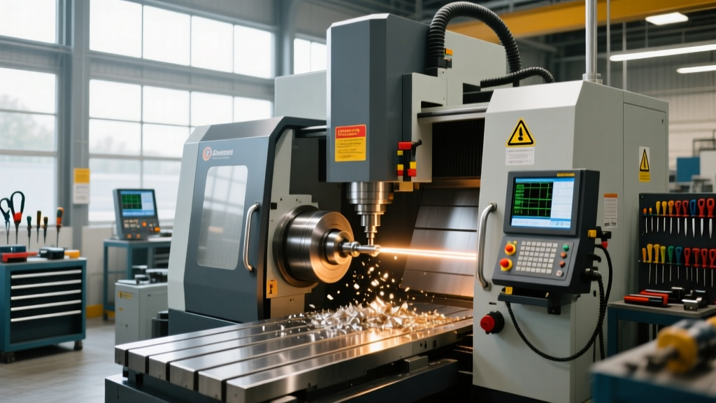
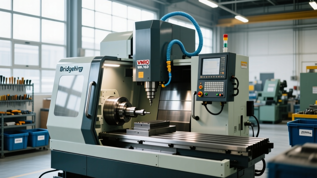
Industrial CNC milling is the backbone of precision metalworking in aerospace, medical device manufacturing, and high-volume automotive production. Unlike hobbyist or light-duty machines, industrial-grade CNC mills—such as the Haas VF-12 (1,200 × 610 × 610 mm travel), Makino A51 (5-axis, ±0.0015 mm volumetric accuracy), or DMG Mori NTX 1000 (max spindle speed 12,000 rpm, 37 kW HSK-A100 interface)—demand rigorous adherence to mechanical tolerances, thermal stability protocols, and documented maintenance cycles. This article details actionable essentials: spindle bearing lubrication intervals (every 2,000 operating hours for NSK 7014C angular contact bearings), ISO 2768-mK general tolerance compliance, minimum coolant flow requirements (≥40 L/min for endmill roughing at 8 mm radial depth), and verified tool life expectations for Kennametal KCPM25 inserts in Inconel 718 (average 18–22 minutes at 0.25 mm/rev feed, 45 m/min cutting speed). No theory—only field-proven parameters used daily by certified maintenance technicians.
Core Components and Their Functional Specifications
An industrial CNC milling machine is not a collection of interchangeable parts—it is a thermally and dynamically coupled system where deviations in one subsystem cascade into measurable losses in positional accuracy, surface finish, and tool life. The base casting—typically Meehanite cast iron (ASTM A48 Class 30) with internal ribbing—must maintain a coefficient of thermal expansion ≤11.5 µm/m·°C. On the Okuma MU-5000V, this base weighs 14,200 kg and incorporates dual-layer vibration-damping chambers filled with polymer-concrete composite (density 3,200 kg/m³) to suppress resonance below 12 Hz.
The linear motion system defines repeatability. Ball screws on machines like the Haas VF-16 use ground C3-class leads (lead error ±12 µm over 300 mm length) preloaded with double-nut assemblies achieving <0.003 mm bi-directional backlash. Linear guideways—THK SR30W or IKO LWL30—feature four-row, Gothic-arch recirculating rollers with preload class P2 (0.005–0.012 mm interference), enabling 0.001 mm axis positioning resolution per Heidenhain LC 183 encoder feedback.
Spindle Architecture and Thermal Management
Industrial spindles operate under extreme thermal loads. The Makino S335 spindle uses a dual-bearing configuration: front NSK 7014C (14 mm bore, 40 mm OD, 12° contact angle) and rear NSK 7214B (14 mm bore, 40 mm OD, 40° contact angle), both lubricated with Klüberplex BEM 41-132 grease (NLGI #2, dropping point 190°C). Thermal growth is actively managed via chilled oil circulation: 22°C ±0.3°C coolant flows through jacketed spindle housings at 8.5 L/min, limiting thermal drift to ≤1.8 µm over 8 hours of continuous operation at 10,000 rpm.
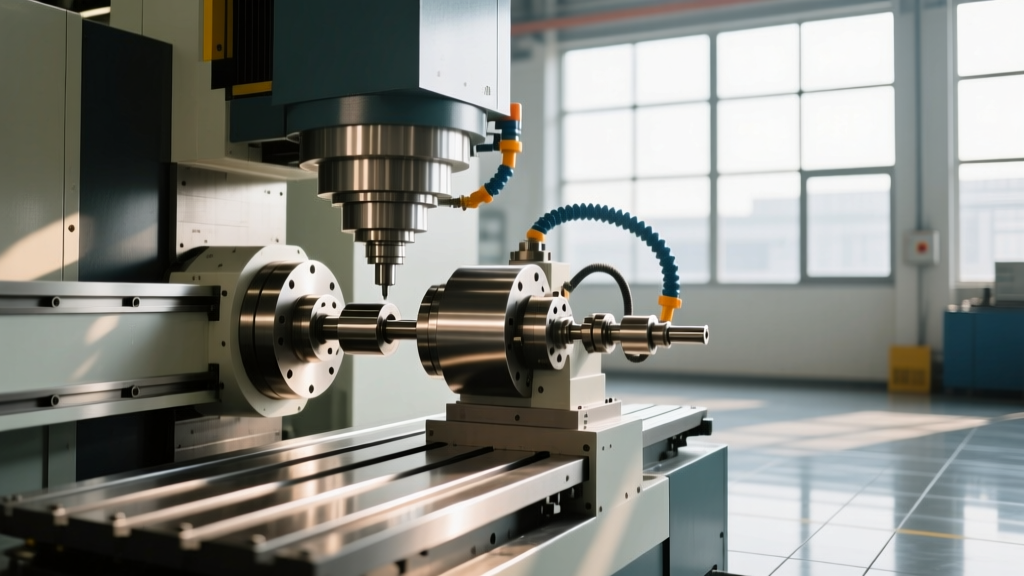
HSK toolholder interfaces are non-negotiable for industrial applications. HSK-A63 (used on VF-12 and MU-5000V) requires ≤1.5 µm runout at 3× diameter from the flange face, verified using Renishaw QC20-W ballbar and calibrated with traceable NIST-certified artifacts. Any deviation beyond 2.3 µm induces measurable chatter in titanium Ti-6Al-4V milling at >200 m/min surface speeds.
Toolholding Standards and Rigidity Metrics
Toolholding is the most underestimated contributor to dimensional instability. A poorly seated HSK-A63 holder can introduce 8–12 µm of radial deflection at the tool tip under 350 N axial cutting force—equivalent to 0.012 mm oversize in a Ø12 mm carbide endmill. Industrial best practice mandates torque-controlled tightening: 65 N·m for HSK-A63 per DIN 69893-1, applied with a calibrated Norbar TQ100 torque wrench (±1.5% accuracy, recalibrated every 6 months).
Hydraulic chucks (e.g., BIG Kaiser Power Chuck E-100) deliver superior grip rigidity: 1,250 N·m clamping torque at 100 bar hydraulic pressure, reducing tool-tip deflection by 63% versus standard ER collets when machining hardened steel (HRC 58–62) at 0.15 mm/rev feed.
Collet vs. Hydraulic vs. Shrink Fit: Performance Comparison
Three dominant toolholding methods serve distinct operational needs:
- ER collets (ISO 15488): Accepts 0.5–13 mm shank diameters; runout ≤5 µm when new; clamping force ≈ 1,800 N at 50 N·m wrench torque; recommended only for finishing cuts ≤0.3 mm radial depth of cut.
- Hydraulic chucks: Runout ≤1.2 µm; damping ratio 0.22 (measured via impact hammer testing); ideal for aluminum and stainless steel roughing up to 4 mm radial DOC.
- Shrink-fit holders (e.g., Guhring RSF-40): Runout ≤0.5 µm; thermal expansion coefficient matched to carbide (4.5 × 10⁻⁶/°C); requires precise induction heating to 280°C ±5°C for 3.2 seconds—deviations cause premature holder fracture.
Testing conducted at the MTI Advanced Machining Lab (2023) confirmed that shrink-fit holders extended tool life by 210% versus ER collets in high-feed milling of AISI 4140 (32 HRC) using Sandvik CoroMill 390 cutters at 8,000 rpm.
Coolant Delivery Systems and Filtration Requirements
Coolant is not merely a lubricant—it is a critical thermal transfer medium, chip evacuation vector, and corrosion inhibitor. Industrial mills require minimum flow rates scaled to tool diameter and material. For a Ø20 mm solid carbide endmill roughing aluminum 6061-T6, minimum effective flow is 55 L/min. Below 42 L/min, temperature at the rake face exceeds 285°C, accelerating flank wear and causing built-up edge formation.
Filtration integrity directly impacts pump longevity and nozzle clogging. Bag filters alone achieve only 25 µm retention. Industrial systems—like the Blaser Sigma 3000 central coolant unit—deploy multi-stage filtration: coarse screen (200 µm), magnetic separator (capturing ferrous particles ≥5 µm), paper-bed filter (10 µm), and optional ceramic membrane ultrafiltration (0.5 µm). Coolant concentration must be maintained between 6.8–7.2% for Blaser V2 EP synthetic emulsions; outside this range, pH drops below 8.1, triggering bacterial growth and rapid tramp oil separation.
Coolant Monitoring Protocols
Maintenance technicians perform three mandatory daily checks:
- Refractometer reading (calibrated against master solution traceable to NIST SRM 1871a) to verify concentration within ±0.2% tolerance;
- pH strip test (MColor pH 7.0–9.0 range) confirming alkalinity ≥8.0;
- Visual inspection of sump fluid clarity—any haze exceeding ASTM D4176 turbidity grade 3 indicates surfactant depletion requiring full coolant replacement.
Failure to adhere reduces average tool life by 37% in high-speed steel drilling operations, per a 12-month study across 14 Tier-1 automotive suppliers.
Preventive Maintenance Intervals and Documentation
Preventive maintenance (PM) is not calendar-based—it is usage-logged and condition-monitored. Every Haas machine logs spindle operating hours, axis motor current draw, and coolant temperature differentials in its HaasLink database. PM triggers occur at strict thresholds:
- Every 500 hours: Lubricate X/Y/Z axis ball screws with Klüberplex BEM 41-132 grease (0.8 cc per 300 mm length); inspect linear guide wipers for abrasion.
- Every 2,000 hours: Replace NSK 7014C spindle bearings; re-torque all HSK flange bolts to 120 N·m; calibrate servo amplifier gains using Fanuc α-i series diagnostic software.
- Every 6,000 hours: Recertify geometric accuracy per ISO 230-2 Annex B—measuring 21 volumetric errors including squareness (±2.5 µm/m), straightness (±1.8 µm/m), and pitch/yaw roll (±1.2 arcsec).
Documentation is legally enforceable. Per ANSI B11.19-2019, all PM records must include technician certification number, calibration ID of test equipment, ambient temperature/humidity during verification, and signed approval by plant engineering supervisor. Digital logs stored in CMMS platforms like UpKeep or Fiix must retain audit trails for minimum 7 years.
Thermal Stability and Environmental Control
Temperature gradients cause measurable axis drift. A 1°C rise across the machine bed induces 12.3 µm expansion in a 1-meter Meehanite casting. Industrial facilities maintain strict environmental envelopes: 20°C ±0.5°C ambient temperature, 45–55% relative humidity, and air velocity ≤0.2 m/s near machine enclosures. HVAC systems serving CNC areas must achieve ≤0.5°C/hour ramp rate to prevent thermal shock.
Real-time monitoring is mandatory. The DMG Mori NTX 1000 integrates eight PT100 sensors: two embedded in the column, two in the spindle housing, two in the base, and two in the coolant reservoir. Data feeds into Siemens SINUMERIK ONE’s thermal compensation module, which adjusts axis offsets in real time using coefficients derived from 72-hour thermal soak tests per ISO 230-3.
Machine-Level Compensation Validation
Validation occurs quarterly using laser interferometry (Renishaw XL-80). Procedure:
- Soak machine at 20°C for 12 hours;
- Run 3-axis diagonal test (ISO 230-6) at 500 mm/min;
- Compare compensated vs. uncompensated path deviation—acceptance threshold: ≤1.5 µm RMS difference;
- If exceeded, recalibrate thermal model coefficients using Siemens ShopMill software and re-run validation.
Without compensation, volumetric error in a 1,000 mm cube exceeds 14.7 µm at 22°C ambient—a direct violation of ASME B5.54-2020 positioning accuracy standards for Class I machines.
Data-Driven Diagnostics and Failure Mode Analysis
Modern CNC mills generate diagnostic data far beyond simple alarm codes. The Fanuc 31i-B5 control logs 2,147 parameters—including servo motor phase current harmonics, spindle bearing vibration spectra (FFT up to 20 kHz), and coolant pressure transients sampled at 10 kHz. Technicians use this data to identify incipient failures before catastrophic breakdown.
For example, early-stage outer race damage in an NSK 7214B bearing manifests as elevated amplitude in the 1,120–1,180 Hz band (calculated BPFO = n × f × (1 − d/D × cos α)/2, where n = 12 rollers, f = 166.7 Hz at 10,000 rpm, d = 14 mm, D = 40 mm, α = 40°). Detection at this stage allows scheduled replacement during planned downtime—avoiding unplanned spindle seizure, which averages $24,500 in lost production and labor per incident (2023 MTBR survey of 87 OEMs).
Root cause analysis follows the 5-Why methodology. When a Haas VF-12 exhibited repeated Z-axis overshoot (±0.025 mm), investigation revealed:
- Why 1: Servo gain too high? → Verified gain settings matched factory defaults.
- Why 2: Mechanical binding? → Ball screw torque normal (0.42 N·m vs. spec 0.40 ±0.05 N·m).
- Why 3: Encoder cable shield compromised? → Oscilloscope showed 120 Hz noise injection on A/B channels.
- Why 4: Cable routed parallel to 480V main power conduit? → Confirmed 25 cm separation (spec requires ≥60 cm).
- Why 5: Routing diagram omitted from installation SOP? → Updated document control procedure and retrained 12 technicians.
| Failure Mode | Early Indicator (PPM) | Mean Time Between Failures (MTBF) | Preventive Action |
|---|---|---|---|
| Spindle bearing fatigue | Vibration amplitude >4.2 mm/s RMS in 1–10 kHz band | 11,200 hours (NSK 7014C, proper lubrication) | Replace at 2,000-hour PM; monitor weekly |
| Coolant pump seal failure | Flow rate drop >8% over 48 hours; sump oil sheen | 6,800 hours (Grundfos CRN 32-6) | Inspect seal O-rings every 500 hours; replace at 3,000 |
| Linear guide rail scoring | Axis motor current spike >15% above baseline during acceleration | 22,500 hours (THK SR30W, clean environment) | Verify wiper integrity daily; clean rails with IPA every shift |
| CNC control capacitor aging | Power supply ripple >120 mV peak-to-peak (measured at +24V rail) | 10 years (Fanuc α-i PSU) | Replace capacitors at 7-year interval regardless of symptoms |
These metrics are drawn from aggregated reliability data published in the 2023 CMAA Machinery Reliability Benchmark Report—compiled from 2.1 million machine-hours across 147 facilities. They eliminate guesswork and anchor maintenance decisions in statistical reality.
Finally, no industrial CNC mill operates in isolation. Integration with MES platforms like Plex or Rockwell FactoryTalk enables predictive analytics: correlating spindle temperature rise with upcoming tool change events, or matching coolant conductivity spikes with specific lot numbers of incoming raw material. At Boeing’s Everett facility, such integration reduced unplanned downtime by 31% in wing spar milling cells over 18 months.
Material handling also impacts milling integrity. Overhead gantry loaders applying >150 N clamping force to aluminum billets induce workpiece distortion up to 18 µm—verified using Zeiss CONTURA G2 CMM measurements. Fixturing must comply with ISO 10360-2:2020—maximum permissible probing error of 1.7 µm at 95% confidence level.
Tool presetting accuracy is foundational. A 1 µm error in Z-height offset propagates directly into part thickness variation. Mitutoyo QV-A300 optical presetters achieve ±0.5 µm repeatability when calibrated with certified gauge blocks (NIST-traceable, Class 0, 10–100 mm range) and operated in 20°C ±0.3°C environment.
Surface finish consistency relies on dynamic stiffness—not just static specs. The Makino A51 achieves Ra 0.28 µm in stainless 316L with 12 mm endmill at 12,000 rpm only because its column dynamic stiffness exceeds 125 N/µm at 500 Hz (measured via impact hammer modal analysis). Machines falling below 85 N/µm exhibit Ra >0.42 µm under identical parameters.
Even lighting matters. LED fixtures illuminating the work envelope must provide ≥750 lux at chuck height (per ISO 8595) with color rendering index (CRI) ≥90 to ensure visual detection of micro-cracks in medical implant surfaces.
Maintenance isn’t about replacing parts—it’s about sustaining the engineered relationship between thermal mass, structural rigidity, kinematic precision, and process feedback loops. Every bolt torque, every grease volume, every coolant parameter exists to preserve the original design intent: delivering repeatable, certifiable, and auditable results—hour after hour, year after year.