How Do You Program a CNC Machine on a Smart Grid? 2026 Electrical Setup Trends
Explore 2026 smart grid electrical setups for CNC machines. Learn power requirements, IoT monitoring, and voltage stabilization before you program.
When facility managers ask, 'How do you program a CNC machine to adapt to real-time grid fluctuations?' the answer begins at the main electrical disconnect. In 2026, CNC machining is no longer just about G-code and spindle speeds; it is deeply integrated with facility-wide smart grid technology. A perfectly optimized toolpath will instantly fail if the underlying electrical power setup suffers from harmonic distortion, voltage sags, or inadequate KVA (Kilovolt-Ampere) sizing.
⚠️ Critical Warning: A voltage sag of just 8% on a 480V 3-phase line (dropping to 441V) will trigger instantaneous servo alarms on modern FANUC and Siemens controllers, halting the spindle mid-cut and potentially scrapping a $15,000 aerospace titanium forging. Power conditioning is a programming prerequisite.The 2026 Baseline: 3-Phase Power and Smart Transformer Sizing
The foundation of any CNC power setup is the isolation transformer and the main disconnect. Modern 5-axis machining centers and multi-tasking lathes draw massive inrush currents when spindle accelerators and coolant pumps engage simultaneously. Sizing the transformer strictly to the machine's running KVA is a legacy mistake that leads to nuisance tripping.
According to the U.S. Department of Energy's Advanced Manufacturing Office, modern smart factories are oversizing isolation transformers by 20% to accommodate regenerative braking feedback from spindle motors, which can push transient voltage spikes back into the facility grid.
CNC Model Power Requirements & Smart Breaker Specifications
| CNC Machine Model (2025/2026) | Required KVA (Running) | Recommended Transformer Size | Smart Breaker / IoT Meter Spec |
|---|---|---|---|
| Haas UMC-750SS (5-Axis) | 35 kVA | 45 kVA (480V 3-Phase) | Schneider PowerLogic PM5560 |
| Mazak INTEGREX i-500 | 68 kVA | 85 kVA (480V 3-Phase) | ABB Ability E4X Analyzer |
| DMG MORI NLX 2500 | 42 kVA | 55 kVA (480V 3-Phase) | Siemens SENTRON PAC4200 |
IoT Power Monitoring: Bridging Electrical Setup and CNC Programming
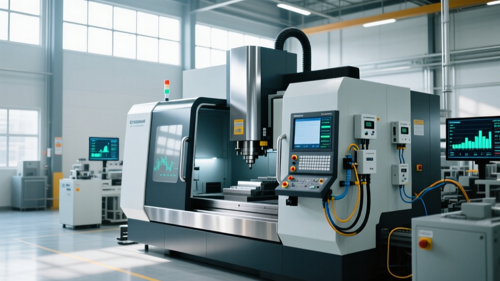
The most significant technology trend in 2026 is the integration of IoT (Internet of Things) power meters directly into the CNC controller's logic board. Operators no longer rely on facility-level SCADA systems to monitor power; the CNC machine itself reads the electrical telemetry.
By installing an IoT power monitor like the Schneider PowerLogic PM5560 (approximately $3,200 installed) at the machine's main disconnect, the CNC controller can poll real-time data via Modbus TCP/IP. This answers the complex question of how do you program a CNC machine to be 'grid-aware'. Using FANUC Macro B or Siemens Sinumerik G-code, programmers can write custom M-codes that check the facility's voltage stability before initiating heavy roughing cycles.
Step-by-Step: Programming a Grid-Aware Custom M-Code
Below is a practical framework for programming a FANUC controller to read an external IoT power meter and pause the machine if Total Harmonic Distortion (THD) exceeds 5%, a threshold that causes severe surface finish degradation in hard milling.
- Establish Modbus TCP/IP Handshake: Map the IoT meter's THD register (e.g., Register 40015) to a FANUC digital input or macro variable using the FOCAS library or built-in Ethernet/IP functions.
- Assign the Macro Variable: Map the incoming Modbus data to system variable #100. (e.g., #100 = [THD_Percentage]).
- Write the Conditional M-Code: Create a custom macro (e.g., M55) that evaluates the variable before the roughing pass.
O9010 (CUSTOM M55 - GRID CHECK)
IF [#100 GT 5.0] GOTO 99 (IF THD > 5%, SKIP TO ALARM)
M99 (RETURN TO MAIN PROGRAM)
N99
#3000 = 1 (GRID DIRTY: THD EXCEEDS 5%)
- Implement in Main Program: Call
M55immediately before heavy load operations like adaptive clearing toolpaths.
Harmonic Mitigation and Active Front End (AFE) Drives
Standard Variable Frequency Drives (VFDs) used on CNC spindle motors and high-pressure coolant pumps are notorious for creating 'dirty power'. They chop the AC sine wave, introducing harmonic currents that overheat facility transformers and cause erratic behavior in sensitive CNC encoder feedback loops.
According to NIST's Advanced Manufacturing guidelines, maintaining compliance with IEEE 519 standards for harmonic control is mandatory for modern smart factories. In 2026, the standard solution is the Active Front End (AFE) drive. Unlike passive line reactors that merely choke harmonics, AFE drives use IGBTs (Insulated-Gate Bipolar Transistors) on the input side to draw near-perfect sinusoidal current from the grid, keeping THD below 3%. Furthermore, AFE drives allow the CNC spindle to act as a generator during rapid deceleration, feeding clean, in-phase power back into the facility grid, effectively lowering the shop's peak demand charges.
💡 Tech Trend Insight: Upgrading a standard 30kW spindle drive to an AFE configuration costs roughly $8,500 in hardware, but the regenerative energy savings and elimination of scrapped parts due to encoder noise typically yield an ROI within 14 months for 24/7 production environments.Troubleshooting Power-Induced G-Code Faults
Even with optimal setups, electrical anomalies occur. Programmers and maintenance teams must distinguish between mechanical G-code errors and electrical power faults. Misdiagnosing a power sag as a programming error wastes hours of debugging time.
Common Electrical Alarms vs. Programming Errors
| Symptom / Controller Alarm | Root Cause (Electrical) | Corrective Action |
|---|---|---|
| FANUC Alarm 401 (Servo Amp Not Ready) | Voltage sag on the 200V control circuit derived from the main transformer. | Check transformer tap settings; install a constant voltage transformer (CVT) for the control cabinet. |
| Siemens Alarm 25201 (Axis Contouring Error) | High-frequency harmonic noise corrupting the glass scale encoder signals. | Verify shield grounding on encoder cables; install 5% impedance line reactors on adjacent VFDs. |
| Spindle Speed Fluctuation during Rigid Tapping | DC bus voltage ripple in the spindle amplifier due to failing filter capacitors. | Replace DC bus capacitors in the spindle drive; do not alter the rigid tapping G-code (G84). |
Grounding and Safety in High-Tech CNC Environments
As CNC machines become more electrically complex, proper grounding transitions from a safety requirement to a functional necessity. A standard ground rod is insufficient for high-frequency CNC noise. Modern setups require a dedicated, insulated ground wire (often green with a yellow stripe) run directly back to the main facility ground bus, completely isolated from the conduit that acts as the ground for standard building lighting.
The Occupational Safety and Health Administration (OSHA) strictly enforces grounding protocols, but in the context of CNC precision, a poor ground creates a 'ground loop'. Ground loops introduce micro-voltages into the CNC's low-voltage I/O boards, causing phantom inputs—such as the machine registering a 'door open' or 'tool unclamp' signal mid-cycle, aborting the program. Ensuring a single-point star grounding topology for the CNC cell eliminates these ghost electrical faults.
Ultimately, mastering the electrical setup is the invisible prerequisite to mastering CNC programming. The most advanced 5-axis toolpaths and adaptive clearing algorithms are entirely dependent on clean, stable, and intelligently monitored electrical power.