How Do CNC Machines Work? Subtractive vs. Additive Alternatives
Understand how CNC machines work by comparing subtractive milling and turning kinematics against 3D printing and manual machining alternatives.
The Core Mechanism: Translating G-Code to Kinetic Energy
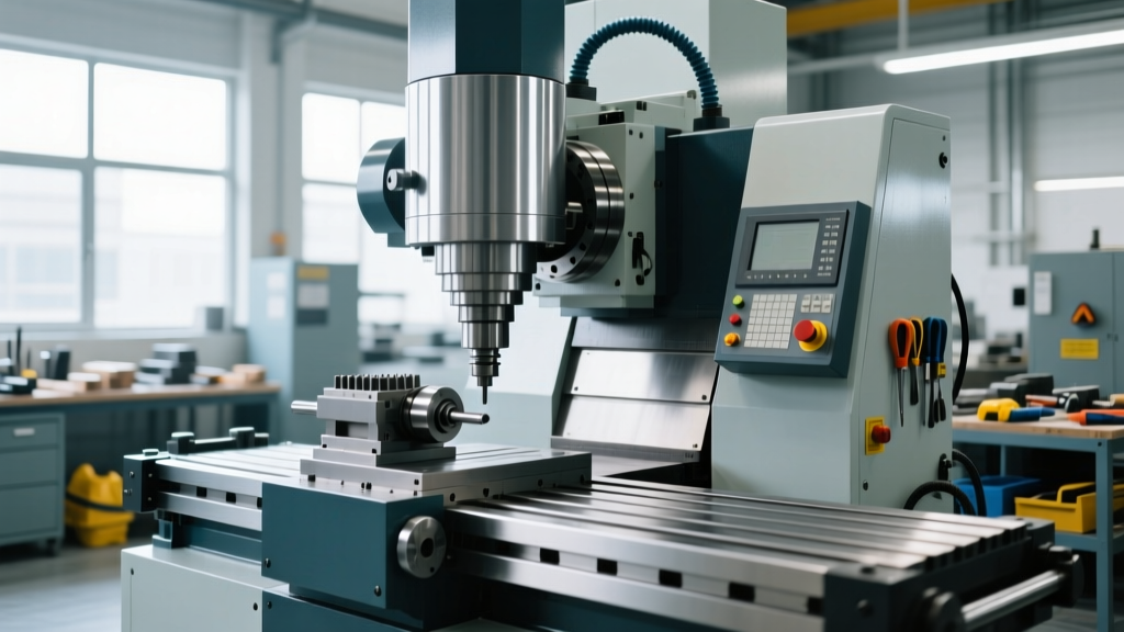
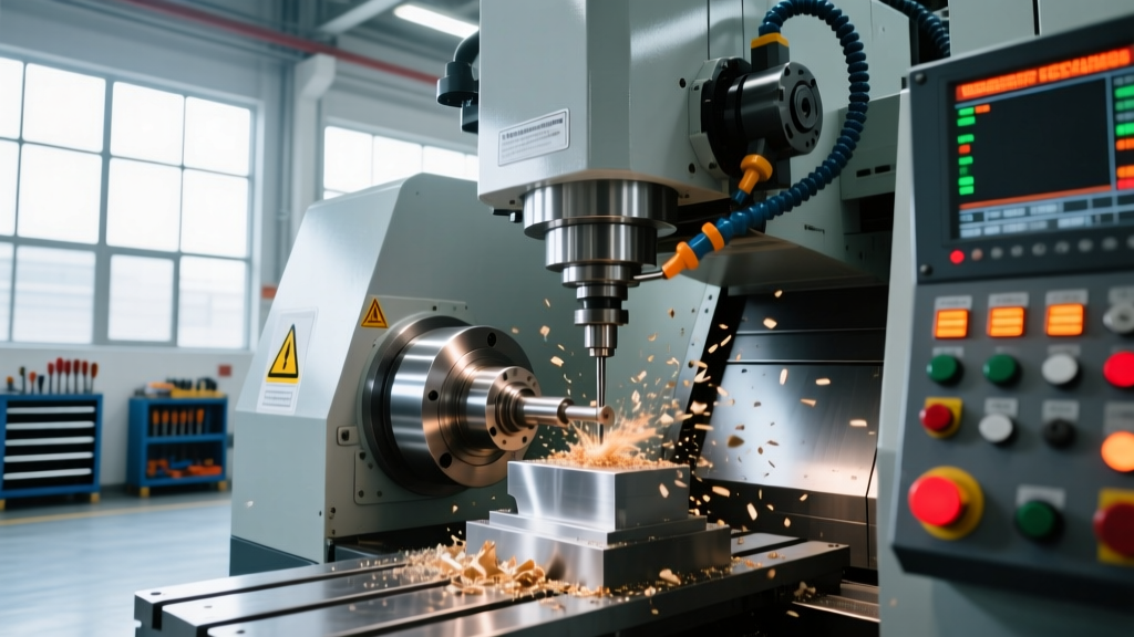
When engineers and machinists ask how do CNC machines work, the answer requires looking past the cutting fluid and metal chips. At its core, Computer Numerical Control (CNC) is a closed-loop electromechanical system that converts digital coordinates into precise physical motion. Unlike manual machining, where a human operator turns handwheels to move the cutting tool, a CNC machine relies on a hierarchical control architecture.
The process begins with CAM (Computer-Aided Manufacturing) software generating G-code. This alphanumeric language dictates toolpaths, spindle speeds (S-values), and feed rates (F-values). The machine's controller—such as a Fanuc 31i-B5 or Siemens Sinumerik 840D—acts as the brain. It reads the G-code blocks and uses an interpolator to calculate the exact trajectory required to move multiple axes simultaneously.
The Closed-Loop Servo System
The controller sends low-voltage command signals to servo drives (e.g., Yaskawa Sigma-7). These drives amplify the signal to power AC servo motors. Crucially, high-precision optical encoders mounted on the motors and linear scales on the machine ways continuously read the actual position and feed it back to the drive. If the physical position deviates from the commanded position by even 0.0001 inches, the drive instantly adjusts the current to correct the error. This continuous feedback loop is what allows CNC machines to hold tolerances of ±0.0005 inches consistently.
How Do CNC Mills and Lathes Work? A Kinematic Comparison
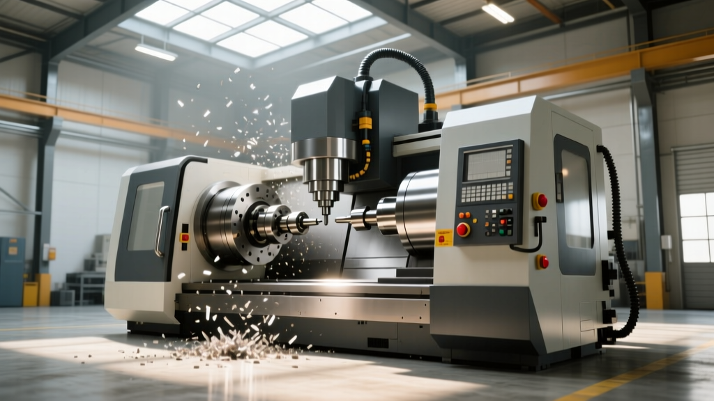
While the control logic remains consistent, the kinematic execution differs vastly between the two primary subtractive CNC categories: mills and lathes. Understanding how do CNC machines work requires distinguishing between rotating-tool and rotating-workpiece dynamics.
| Feature | CNC Vertical Mill (e.g., Haas VF-2SS) | CNC Lathe (e.g., Mazak Quick Turn 250) |
|---|---|---|
| Primary Kinematic Motion | Tool rotates (up to 12,000 RPM); part is stationary on the table. | Part rotates in the chuck (up to 4,000 RPM); tool is stationary. |
| Standard Axes | 3 linear (X, Y, Z), expandable to 5-axis with trunnion table. | 2 linear (X, Z), expandable to Y-axis and live-tooling (C-axis). |
| Optimal Geometry | Prismatic parts, pockets, 3D contours, mold bases. | Cylindrical, conical, and radial symmetry (shafts, bushings). |
| Approximate Base Cost (2026) | $82,000 - $95,000 | $140,000 - $180,000 |
In a 5-axis CNC mill, the controller must calculate RTCP (Rotary Tool Center Point). As the rotary axes (A and C) tilt the workpiece, the controller dynamically offsets the linear X, Y, and Z axes to keep the tip of the cutting tool exactly on the programmed surface. This requires massive processing power and ultra-rigid mechanical components to prevent chatter.
Subtractive CNC vs. Additive Alternatives (3D Printing)
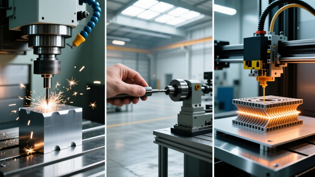
To fully grasp how do CNC machines work in a modern manufacturing ecosystem, we must compare subtractive kinematics against additive manufacturing (AM). While CNC removes material from a solid billet to reveal the part, metal 3D printing (like Selective Laser Melting - SLM) builds parts layer by layer using a high-power fiber laser melting metal powder.
The Economics of Scale: CNC vs. SLM vs. FDM
The fundamental difference in how these machines work dictates their economic viability across different production volumes. CNC machining involves high setup costs (fixturing, CAM programming, tool probing) but low marginal costs per part. Additive manufacturing features near-zero setup time but high marginal costs due to slow build rates and expensive powder.
| Production Volume | CNC Machining (6061-T6 Aluminum) | Metal SLM (EOS M 290 - AlSi10Mg) | Industrial FDM (Stratasys F370 - ABS-CF10) |
|---|---|---|---|
| 1 Unit (Prototype) | $350 (High setup amortization) | $180 (No tooling required) | $45 (Fastest lead time) |
| 100 Units (Bridge) | $42 / unit | $165 / unit | $38 / unit |
| 10,000 Units (Mass) | $11 / unit (Optimized cycle) | $140 / unit (Economically unviable) | $32 / unit |
Furthermore, the physical properties of the output differ. CNC machined parts retain the isotropic strength of the original wrought billet (e.g., 6061-T6 yields at 40 ksi). According to research from the National Institute of Standards and Technology (NIST), SLM parts can achieve near-wrought density, but they are prone to anisotropic weakness along the Z-axis build layers and require extensive post-processing (stress relieving, support removal, and surface machining) to achieve CNC-level surface finishes (Ra 32 µin vs SLM's typical Ra 250 µin).
CNC Automation vs. Manual Machining: The Tolerance Gap
Before the proliferation of microprocessors, manual mills like the iconic Bridgeport Series I dominated machine shops. Understanding how do CNC machines work requires contrasting them with these manual predecessors. In manual machining, the operator's physical skill dictates the accuracy. The operator must manually compensate for leadscrew backlash, tool deflection, and thermal expansion.
'A master manual machinist can hold tenths (0.0001 inches) on a single dimension, but holding ±0.0005 inches across a complex 3D contour with 50 distinct features is physically impossible without CNC interpolation and automated backlash compensation parameters.'
— Sandvik Coromant Machining Economics Guide
CNC machines utilize precision ground ballscrews (typically C3 or C5 accuracy class) and pre-loaded bearings to eliminate mechanical backlash. When a CNC machine changes direction, the controller automatically applies a backlash compensation value (e.g., 0.0004 inches) to the servo command, ensuring the physical tool moves exactly as programmed. Entry-level CNC alternatives, like the Tormach PCNC 1100 (approx. $11,500), bring this automated kinematic control to small shops, bridging the gap between manual capability and industrial production.
Decision Matrix: Which Process Fits Your Part?
Choosing between CNC machining, additive manufacturing, and manual operations depends on specific geometric, material, and volume constraints. Use this framework to select the optimal manufacturing method:
- Choose 3+ Axis CNC Milling if: Your part requires tight tolerances (±0.001" or tighter), features prismatic geometry with deep pockets, requires high-strength wrought metals (like 7075-T6 Aluminum or Ti-6Al-4V), and demands excellent surface finishes for sealing surfaces.
- Choose Multi-Axis CNC Turning if: The part is radially symmetric (shafts, fittings, pistons), requires high-volume production from bar stock, and benefits from the extreme rigidity and chip evacuation of a lathe environment.
- Choose Metal 3D Printing (SLM/DMLS) if: The geometry includes internal conformal cooling channels, organic topology-optimized lattice structures, or complex internal manifolds that a rotating or linear cutting tool physically cannot reach.
- Choose Manual Machining if: You are performing a one-off maintenance repair, modifying an existing part where CAD models do not exist, or performing simple facing and drilling operations where the 2-hour CAM programming and setup time of a CNC machine would exceed the 10-minute manual machining time.
Ultimately, how do CNC machines work is a question answered by the intersection of software interpolation and rigid electromechanical execution. While additive technologies continue to evolve for complex prototyping, the subtractive kinematics of CNC mills and lathes remain the undisputed standard for high-precision, high-strength, and scalable industrial manufacturing.